Thursday, January 9, 2020

Addendum on the charger / welder

The new welder arrives!

I ordered one of the cheapest inverter welders I could find on Amazon that had a decent power output and duty cycle.

"Arc Welder Dual Voltage 110V-220V IGBT Inverter DC Welding Machine 200A High Frequency Household Smart Welder for Novice Welders fits below 3.2mm weling rods"


Cost was $119.00 not including tax. For comparison, the battery charger I previously had (which I went through two of them!) was $179.00. It also had no monitoring or charging customization (which I have via the MPPT). It also was not nearly as efficient in converting grid power to charge power. It was also limited to 40 amps.

While the previous charger was using around 15 amps, this was drawing a little over 9 amps for the same output to the MPPT. This makes it safe to use with a "smart plug" which is rated for 15 amps.

Results


The graph above is what I would call a "mixed day". I had solar input, but it was spotty and because of this and my old batteries, I had to top them off with the welder. What you see in the graph is input from the panels from 9:00am until dark at 6:00pm and then the welder coming online at around 6:30pm until around 9:00pm.

Note that I am still running parallel MPPT's. Because of this the welder began the full 4 stage cycle all over again because it was a different MPPT. Another thing I will bring to your attention is the voltage drop at about 5:30pm. This is very indicative of a bad cell or battery in the chain.

Summary

As long as things keep up like this, and there are no surprises, I doubt I will ever go back to a separate grid charger. Not only was my experience with that horrible, but the experience with this is so far wildly better than expected.

Addendum 1-11-2020

Yesterday I had windows installed on my house. Because of this I had to disconnect and move the panels. This gives me a "trace" on the system with only the welder as a charger (without suppliment from the panels) for a 24 hour period.


There are a couple "telling things" from this trace. The biggest thing is the overall condition of the batteries.

What this has been telling me about the batteries is I somewhere have a weak or dead cell. This can be seen by how the quickly voltage pulls down but then stabilizes. The other telling thing is the intervals of voltage drop. I still dont know for sure what these are but my speculation is that is the defrost cycle on the fridge (the only load on the system).

As for the charge cycle, this tells me that this setup will be very good for litium batteries. What you are seeing is what the batteries can readily absorb. This is shown by the low voltage and high wattage (blue being volts, green being watts). As the voltage reaches its peak you can see the wattage dropping off rapidly. This is followed by welder shutoff and then the fall off of the "skin charge" on the batteries (most likely by another defrost cycle).

Since its a crappy day weather wise, I think I will leave the panels disconnected. Tonight I will run a charge cycle but will keep an eye on the voltage level. After the "peak" I will then shut down the welder and see how the batteries hold up without a long "equalize" cycle. If my hunch is right, then I may be able to reach a "full days charge" with 1 1/2 hours of charging. That would actually be closer to what I saw with charge versus discharge wattage.

Addendum 1-16-2020

Below is the 12 hour trace of todays power. The first item of note is the PV panels and the welder/charger running at the same time. with a low light day the second is the evening top off with only the welder/charger providing power.


This is what the readout looks like when running the two MPPT's in parallel


Tuesday, January 7, 2020

Dont overlook "waste heat" especially in lighting!

We've all most likely hear of the term "waste heat". You will have most likely have heard about it concerning incandescent light bulbs. We all have heard that LED's "efficiency" comes because it delivers mostly light and not heat. The problem with this though is we need to temper our idea of "waste heat".

What truly is "waste heat"?

We really need to take a look at what we consider as waste heat. We need to rethink the whole concept and put it into perspective. What waste heat really is, is heat that is brought into a space we are trying to cool, or dumped out of a space we are trying to warm. With this in mind, is an incandescent light bulb really as inefficient as advertised?

Now this isn't really about incandescent light bulbs versus LED's. I use this as the example that is most likely known to the most diverse audience. If it is the middle of winter, and you are heating a space, the electricity that is being "lost" to heat, is going as heat into the space we are heating. This somewhat reduces the load on our other heat sources. In essence, the light bulb is working in conjunction with our main heater to warm our space. In essence, that bulb is working not only as a light source, but also as a restive heating element (like an electric space heater).

Now likewise, in the summer when we are trying to cool our space, that light bulb is like having a space heater running. Under those circumstances our cooling system has to work harder to get rid of that unwelcome heat. It is under these circumstances where incandescent bulbs are inefficient and LED's "win the day".

One "tool" two purposes

With winter upon us, we have a much larger need for two things. These would be light and heat. Most people of the younger generation are likely to think that this would require two separate "tools". Incandescent bulbs are not going to significantly contribute to heating our space. Additionally, if you are "off grid" you understand that electric heating would be very expensive indeed because of the extra capacity in generation and storage of electricity necessary.

There is a solution though that provides both heat AND light. This solution hearkens back to the days of camping (before you took your whole house with you to "camp"). This would be the mantle lamp. Despite there being different types and manufacturers, most would refer to these as "Coleman Lamps". When you use this term though, most will picture the old green lantern that you had to constantly pump up.
Not only does this lamp provide (maybe harsh) light, but best of all it provides light AND heat. The problem is though that people think this (or its propane canister version) is the only option. 

Fortunately this is not the case. There are not only other options than the old green Coleman lantern, but there is at least one other option from pressure lamps altogether.
Front and center is the liquid fuel Coleman table lamp. Most people (including myself at one point) had no idea that Coleman made "table lamps" for use in the house. It seems these were particularly popular in Canada (Im assuming for the same reason I am featuring them here). They operate in the same way as the camping lantern. If you can use a Coleman camping lantern you can use these.

CAUTION!

Keep in mind that most of the coleman table lamps will be from the 50's or earlier and may need some repair or at least maintenance. The one pictured above is a 1948 model. One thing to note, some come with a built in pump but the really old ones use a separate hand pump. Try to stick with the ones with the built in pump. Also keep in mind that these were built long before government had to protect us from everything. They are dangerous if mishandled. For this reason dont ever light one inside or on a flammable surface.

The "other" option.

Note the lamp behind and to the left of the Coleman. This is an Aladdin brand kerosene wick type lamp. These are not quite as bright as the Colemans. On the positive side however there is no "pumping" required. They are basically just a standard kerosene lamp with an efficient burner and a mantle. One other very positive note is that they dont stink like a cheap kerosene oil lamp (at least until you blow them out for a short time as it cools).

Other items of note concerning the Aladdins. The wick must be kept in good order or it will burn and light unevenly. There is a special wick cleaning tool that I HIGHLY recommend you have on hand. Also NEVER burn one unattended. They tend to be a bit sensitive to wick position. The will also change and need to be turned down as they heat up. The reason for this is that as soon as you start getting a little bit of carbon buildup on the mantle, they will begin to "smoke" and need to be turned down. I learned this the hard way and had a big black soot spot on the ceiling of my living room as a result of being careless and not keeping a close eye on my lamp.

One last note concerning the Aladdins. THEY ARE NOT CHEAP! A new basic model will set you back $125.00+. You can get lucky however and find them second hand. I just picked one up in the south for $100.00 complete with shade. I saw the same one in the store new for $299.00. With that in mind, keep an eye open in antique and second hand stores. Many times these people dont realize what they have.

One last word on the Aladdins, these get so hot that you can light a cigarette by holding it at the top of the chimney. Because of this, leave plenty of room between the top of the chimney and anything that can burn.

The other candidates

These are variations on the Coleman burner. I have so far found two types of these.
The first (white tank) has a bunson burner type of mantle holder. This unit runs on propane. You will note that it mounts directly on and uses the tank as a base. This one is by far my favorite. It is simple to use and other than changing the tank or a broken mantle it is maintenance free. It also has two advantages over the other models. First is there is VERY little odor when it is in operation. Secondly, it puts out plenty of light AND heat. In fact this lamp alone is enough to heat and light the box with no other heater running!

The second, brown tank, is a (reproduction) Coleman type burner and uses Coleman Fuel (white gas) as its source. Operation is the same as a Coleman lamp except you need a separate pump to pressurize the tank (I run 15-20 psi).

One note on these two. They are hard to come by as they are essentially "home made". Prior to LED's solar panels and batteries, these were the mainstay of Amish household lighting. The first generation was the brown white gas model. Second generation was the propane version. Because of this these two are essentially "cottage industry" made lamps. With this in mind, I found this particular Coleman fuel lamp to be on the very dangerous side when lighting it. There is no small diameter pickup tube inside the pipe between tank and burner. Because of this, a LOT of fuel comes out when first started. Its actually a quite spectacular sight to light this one with all the burning fuel not only in the burner but also dripping on the tank.

Final thoughts

With the Coleman lamps and burners I seem to get the best of both worlds, heat AND light. The best of these is the propane tank mounted unit. The downside of this is I dont know a reliable source for these. I found mine by word of mouth through Amish country at an Amish store. It was of course used as it had been replaced by LED's in someones home. It did however sell me on propane as the best all around fuel source.

I found this tank mount propane distribution tree on Amazon however. Note that it is also direct tank mount and has an outlet at the top for a propane lantern. You could also buy a refill adapter and some propane mantle lamps if you dont want the bulk of the tank to carry around.

WARNING!

I keep  a carbon monoxide detector in the "box" just in case. It has not gone off until yesterday. What I found is that if you turn down the propane lamp too far, it WILL produce carbon monoxide. In all this time I have had this only once. That one time was when I was throttled too far back. USE CAUTION with these lamps indoors!

Thursday, January 2, 2020

Charging solar backup batteries with a welder

BEFORE I START, DO NOT TRY THIS WITH AN AC WELDER!!!!


For the past weeks, Ive been considering and designing for ultimately going to LiFePo4 (Lithium) batteries. One of the biggest hurdles I have found is finding not only a high amperage backup charger, but also one that I can get data from for my control system. As it stands my MPPT has all the charge and condition data I need on my batteries. With this not only can I see current state, but also trending of (at the moment) solar input and battery voltage over time. These are the only two parameters I care about at the moment.

I happened to be browsing Quora today and came across this question. In it they ask about using the output from a welder as the input to an MPPT. Ive done some experiments with a converted alternator, bypassing the voltage regulator and using a larger external 3 phase rectifier. With that I would then vary the field to control power output. This was a pain but it worked. My issue is that I have this nice 3 Kw military diesel generator already. Problem is last time I put a charger on it, the charger failed. After this I went back to the engine driven alternator experiment.

Seeing the post linked above and having "napped" on the subject, I realized I have all the pieces to throw together a test. I have a Miller 152 DC (DO NOT CONNECT AN AC WELDER TO AN MPPT!) old model inverter stick / TIG welder. I also have a spare MPPT from my tests with the alternator. Well after tossing it around in my mind, I decided to setup for a test.


I dialed it in to 40 amps and checked the output voltage. ~88 volts DC was what I got, well within the spec of the MPPT (which is around 125 vdc, 40 amps or total (I think) 1050 watts) and within the continuous rating of the welder. I then wired the "welding leads" into the MPPT. I threw the switch. What I saw was nothing short of worth breaking out the Champagne!


The MPPT was staging and dumping 1087 watts of power into the batteries at 28.88 volts (equalize stage). Best of all, there was no undue heating of the batteries nor of the MPPT. Best of all, the "magic smoke" stayed inside all of the electronics!

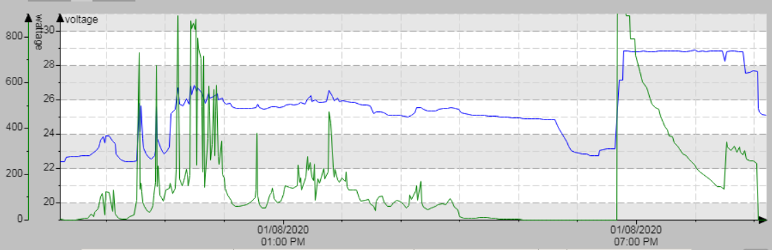
Next to see what actually happened. this is the chart of the whole experience


In the chart, blue represents the battery voltage. The line where it starts is 25 volts (had decent sun today). The green line is the input wattage. it is 0-900 in 100 watt increments. As you might guess, I was at first a bit dissapointed at the output. Then I remembered that the batteries were already at full charge (or close). The first "dip" was from turning on the washer and oil filled heater. The welder was easily powering everything and not putting power to the batteries. With the second dip, I had shut off the welder to let the batteries draw down from the heater. Keep in mind my batteries only have about 20% life left in them so it didnt take long to dip down to 22 volts under the load.

After discharging the batteries some, I fired the welder back up. Note that it immediately went to full power to the batteries to bring them back up. As they were taking charge, you can see the wattage (green line) dropping off as the internal resistance of the batteries increases. Being dark out and running out of time, I went ahead and shut things down having proven it will work.

My next test is to do it over about an hour or two. During this, I will know more about heating and how the whole system reacts under real world conditions. At this point I am confident it can be done without damaging anything. The only real question I have is if the welder will "throttle back"far enough so as not to require a dump load. The basic principle has been proven to my satisfaction, now its just "details".

Addendum 1-3-2020

Today I did a more thorough test. This time I ran for about 7 hours. I couldnt be more pleased with the results


Nice clean charge with the wattage tapering off just fine. At the end of the run I was up to about 93 volts going in and around 100 watts. I also bought a contactless thermometer and noticed nothing unusual with the batteries running at around ambient temperature. The MPPT was running about 72 degrees at its hottest point. At this point, I consider the results better than even what I got out of my original grid connected charger.

I cant comment on other combinations, but I now know my welder with my MPPT has been a complete success. Next to test the welder with the generator, but that is an unrelated subject. If that works I then have a portable welder that I can also use as a backup charger around the homestead.

Addendum 1-4-2020, The Welder and MPPT

Some have wondered about the methodology I used to determine if or how this was going to have a good chance of working. Here I will review a bit about what I checked first before I even connected the wires.

The MPPT

In my system I am running an Epever 4250BN MPPT. Now to me the datasheet is a bit confusing. Some of the ratings just dont add up. Because of this I went with the lowest individual rating values. First of all we have different values based on the battery voltage. This tells me that the MPPT finds current (amperage) as the most important value. This you can see in my other posting about "Amps,Volts, and Watts". Long story short, the electronics care more about the current passing through (wire and electronics sizing) than the voltages. My battery pack and inverter is 24 volts (in my opinion the minimum voltage for a serious system). So now to look at the datasheet....
  • Rated charge current 40 amps (discharge @20 amp I believe is for the dump load)
  • Maximum PV input power 1040 watts. This is what your welder should be set to supply as maximum.
  • Maximum input voltage 138 vdc. (for some reason this is not on the datasheet but in the amazon ad).
It should be noted that I monitor my values from the data bus of the MPPT. You can get approximate values during setup and test with a volt meter and a DC clamp on amp meter. NOTE: not all clamp on meters will do DC. If you are doing a solar system, a DC clamp on amp meter is a MUST in my opinion. Do not use your normal meter in "amps" as most are fused to around 10 amps. A clamp on will take you into the 100's of amps.

The Welder

Next, I look at the data sheet for the welder in question. In my case it is a Miller 152 Maxstar. Everything you need to know is on page 9 (in my case). Here we find
  • 100% duty cycle (meaning it can run continuous) of 125a at 25vdc.
  • Open circuit voltage 95vdc. This is the "no load voltage" verified with my meter.
Next we look at the volt-amp curve. This one is very important. Remember as you draw more amperage the voltage will drop. For the test, I set my current limit to ~40 amps on the welder so as not to accidentally overload the MPPT.

Looking at the output curve, at 40 amps the voltage will drop to about 65 volts. This is still well within the spec for the MPPT. The maximum I saw during my testing on flat batteries was 73.78 volts at 14.74 amps, for 1087 watts. This is slightly above maximum for the MPPT but it was not significantly over rated. I suspect the MPPT was burning some of this off as heat. If I had run at that wattage for a longer period of time, I would have first tried turning down the amperage setting a bit. NOTE: I do NOT know this for a FACT!

Other DC Inverter welders

I just finished searching for other welders of this type. Nowhere could I find a detailed volt/amp curve for the welder in question. I did find some that listed their open circuit voltage. This was usually around 70vdc. The other thing you need to know which I couldnt find is the "duty cycle" at the amperage you need.

What the duty cycle is (in case you dont know) is how long you can power at a given amperage before the machine needs to cool down. Some of what I saw was listed at 75 amps but a 20% duty cycle. What this essentially means is you can run at 75 amps for 2 minutes and then the machine needs to cool for 8 minutes (roughly). All I will say without having the actual data is firstly this is not a "linear value". In other words 37.5 amps will not necessarily give you a 40% duty cycle.

Personally, I wouldnt look at anything below 150 amps or so rating. After all, you may want to also use it as a welder. Most serious welding work is going to happen in the 80-120 amp range.

Update 1-6-2020

My new welder / charger just arrived. I purchased a cheap one off of Amazon. It is a 110/220 vac inverter type. Other than a little lower voltage running on 120vac vs 240vac of the Miller, there was no difference in performance in initial testing. 

The only issue I did see is I had paralleled 2 40a MPPTs last night in preparation. One is on the panels (900 watts) and the other on the welder. Both were connected to the same batteries on the output. There seemed to be some "contention" over which MPPT was going to "run the show" (after a good day of sun).

Despite that minor issue, no magic smoke was released and everything returned to normal when I isolated the input of one or the other. One very pleasant surprise was the power draw of the welder. My previous dedicated charger would pull close to 15+ amps to charge batteries directly. With this method it was pulling only around 9 amps for the same power. In this regard the welder is MUCH more efficient.

Final Thoughts

In todays installment, I pulled my batteries down heavy before starting. I did see the input wattage to the MPPT peak up around 1100 watts for a while. This isnt all that much above MPPT spec. On the other hand it does make me think that the security of having a dump load would be worth the minor expense. Since I dont have a dump load, I cannot tell for sure. Dialing down welder amperage didnt seem to have a lot of effect (neither did dialing it up for that matter) on anything other than voltage.

This gives me an educated guess that the MPPT will only take what it can use off of the welder (MPPT regulating the overall charge side). I did notice some heating (76 deg/f with ambient being around 60 deg/f) of the MPPT. Note that the MPPT does have overtemp protection with shutdown around 150 deg/F.

After testing with another DC inverter welder and 2 40a MPPTs in parallel and seeing the contention between MPPT's, I think I will end up making a minor change to the overall plan. I will go back to one MPPT of higher output capacity with a source transfer switch on the input. I will then set it up so that it is "motorized" for remote switchover. I know I could use relays or contactors but I dont want to waste the power on holding contactors and cant find anything high amperage that is latching.

All in all, I stand by my initial overall conclusions.